Lebanon Wastewater Treatment Plant Operation
![]() Watchdog
Indiana Home Page
Watchdog
Indiana Home Page ![]() Watchdog
Lebanon Home Page
Watchdog
Lebanon Home Page ![]() Lebanon
Sanitary Sewer Backup Prevention
Lebanon
Sanitary Sewer Backup Prevention
Wastewater Treatment Plant Operation Flow Chart
NOTE: Please send an E-mail to taxless3@comcast.net if you wish to receive a Windows Live Photo copy of the flow chart below that is easier to read..
Operation During Normal
Conditions
(Compiled August 25, 2020)
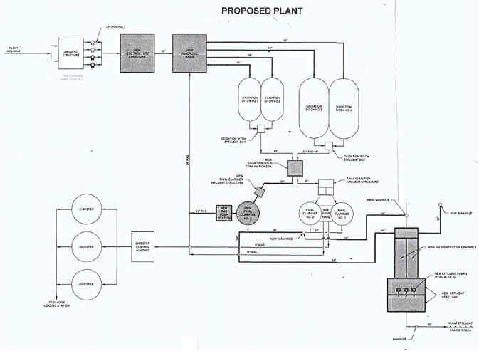
NOTE: The components of the "PROPOSED PLANT" flow chart at the top of this web page are referenced in this description of how the Plant operates during normal conditions.
The Lebanon Wastewater Treatment Plant is located at 802 Lafayette Avenue. This Class III Plant is a 5.0 million gallons per day (MGD) activated sludge treatment facility with a peak design capacity of 15.0 MGD. The Plant’s collection system is 100% sanitary sewer by design, meaning that the sanitary sewer collection system is not designed to accept storm water runoff. Listed next is a description of how the Plant operates during normal conditions (when there is no significant rain event).
(1) Wastewater (raw sewage) influent is delivered to the Plant through a 48-inch
concrete pipe.
(2) The wastewater passes through an influent flow meter in the INFLUENT
STRUCTURE.
(3) Wastewater enters an influent channel in the INFLUENT STRUCTURE and passes through a gate onto a bar screen where most debris and solids are removed immediately upstream of four variable-speed raw sewage pumps. NOTE: The four variable-speed raw sewage pumps have a total pumping capacity of 18 MGD.
(4) The wastewater flows into a wet well where the raw sewage pumps direct the wastewater flow to the HEAD TANK / GRIT STRUCTURE.
(5) All of the wastewater flows through grit removal machinery in the GRIT STRUCTURE.
(6) After grit removal, the wastewater goes into the ANAEROBIC BASIN.
(7) The wastewater stream is then directed to one of the four OXIDATION DITCHES for secondary bio treatment. The oxidation ditches provide an extended air secondary treatment for the biosolids. Each oxidation ditch has a 700,000 gallon capacity, and it takes 12 to 15 days for the microorganisms to complete the secondary bio treatment. All four oxidation ditches are in operation; the only time there is not four oxidation ditches operational is if one is taken off line for cleaning and or maintenance.
(8) The bio treated wastewater goes to one of two OXIDATION DITCH EFFLUENT BOXES.
(9) The wastewater then travels to a OXIDATION DITCH COMBINATION BOX.
(10) The wastewater is directed into two FINAL CLARIFIER INFLUENT STRUCTURES, where it then travels into three FINAL CLARIFIERS where the heavier biosolids are settled and the clear water separated.
(11) The heavier biosolids are pumped by the RAS PUMPS into a return line to the ANAEROBIC BASIN and into a waste line to the DIGESTER CONTROL BUILDING.
(12) The activated sludge in the return line that goes to the ANAEROBIC BASIN helps maintain the bug types and population numbers needed to reduce the solids from the influent stream.
(13) The waste line feeds three DIGESTERS in the DIGESTER CONTROL BUILDING. The DIGESTERS are aerobic tanks that further break down the biosolids.
Excess sludge is dewatered through a centrifuge and is deposited in the SLUDGE LOADING STATION, where the solidified sludge is hauled off by an IDEM-approved contractor.(14) The clear water from the FINAL CLARIFIERS goes to the UV DISINFECTION CHANNELS.
(15) EFFLUENT PUMPS deliver the clear water that has been disinfected by ultraviolet treatment to the EFFLUENT HEAD TANK.
(16) The fully treated effluent is discharged through an effluent flow meter into Prairie Creek.
Operation During Significant
Rain Events
(Compiled August 26, 2020)
NOTE: Some of the components of the "PROPOSED PLANT" flow chart at the top of this web page are referenced in this description of how the Plant operates during significant rain events.
While the sanitary sewer collection system is not designed to accept storm water runoff, storm water does make its way into the Lebanon Wastewater Treatment Plant during significant rain events through (a) improper sump pump and storm water connections to the city’s sanitary sewer system by some Lebanon Utilities customers, (b) leaks in the sanitary sewer lateral connections from some Lebanon Utilities customers to the city’s sanitary sewer system, and (c) some leaks through the sanitary sewer pipes and manholes maintained by the city. Listed next is a description of how the Plant operates during a significant rain event.
The wet well in the INFLUENT STRUCTURE has four variable speed pumps, two of which are all that is needed for normal plant capacity. The other two will act as storm pumps during a significant rain event and are used to pump influent into the Plant.
In the event flows exceed the Plant's 15.0 MGD peak capacity, the influent backs up into the raw sewage delivery system through the 48-inch concrete pipe at the entrance to the INFLUENT STRUCTURE.
![]() Watchdog
Indiana Home Page
Watchdog
Indiana Home Page ![]() Watchdog
Lebanon Home Page
Watchdog
Lebanon Home Page ![]() Lebanon
Sanitary Sewer Backup Prevention
Lebanon
Sanitary Sewer Backup Prevention
This page was last updated on 08/26/20 .